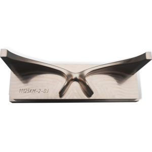
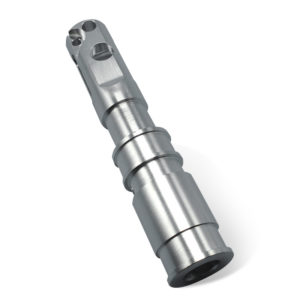
In machining, there is a kind of slope where the distance from the four vertices to the reference plane is not equal, that is to say, the part in the projection of the two directions and the reference plane are at a certain angle, this plane with a spatial slope It is called compound slope, as shown in Fig. 1. Plane ABCD is composite slope, A’B’C’D’ is the reference plane, and ABCD plane is α, β in both directions and A’B’C’D’ plane. Angle, so its processing method is different from ordinary single-slope processing method, it must pass angle conversion to process a qualified compound slope. Common compound ramps include liners for marine engines and clip-on turning tools. China CNC Machining Parts Manufacturers and Factory – Customized
1. Angle relationship of compound slope
Figure 2 shows the compound slope workpiece. The angle between the slope along the X-axis direction and the base surface is α, and the angle between the slope along the Y-axis direction and the base surface is β. The processing needs to use αn and βn. The estimation process is as follows:
Extend AB cross X axis to M, ∠AMO=α; extend BC to MN to E, ∠BEP=β.
In rtΔMBP, tanα=PB/PM, PB=PMtanα, over M for MG, BC for BC in G, and PG, then PG for BC, and ∠GMP=αn.
In rtΔMPG tanαn=PG/PM, PG=PMtanαn.
In rtΔBGP, since PG⊥BC, ∠BGP=βcosβ=PG/PB=PMtanαn/PMtanα.
So tanαn=tanαcosβ.
In rtΔAON tanβ = OA/ON, OA = ONtanβ, over N for NH ⊥ AB cross AB in H, OH, then OH ⊥ AB and ∠ HNO = βn.
In rtΔHON, tanβn=OH/ON, OH=ONtanβn.
In rtΔOHA, since OH⊥AB, ∠HOA=αcosα=OH/OA=ONtanβn/ONtanβ=tanβn/tanβ.
So tanβn = tanβcosα.
2. Composite ramp milling method
(1) Milling key points. To mill a compound bevel, generally the workpiece is first rotated around a certain coordinate axis by a tilt angle α (or β), and then the fixture or cutter is rotated by an angle βn (or αn) and then milled. China CNC Machining Parts Manufacturers and Factory – Customized
(2) Milling method. Use ordinary bench vise to machine on the vertical milling machine: borrow inclined iron or sine gauge, make the work piece tilt α (or β) angle laterally along the workbench, and then make the end of milling head βn (or αn), then you can carry out milling . Machining with a universal bench vise on an upright milling machine: Use a slant horn or sine rule to tilt the workpiece along the jaw vise jaw angle α (or β), and then tilt the universal bench vise along its horizontal axis βn (or Αn) angle, while the vertical milling head is kept perpendicular to the table surface. Milling of composite surfaces using a jig: 1 When milling a composite surface with a fixture on an end mill, the angle between the bottom surface of the fixture and the positioning surface (that is, the positioning angle) and the direction in which the part is rotated on the fixture must be determined (ie, The orientation angle), so that after the installation of the parts, as long as the moving table can be milled compound slope. 2 The calculation process of the positioning angle and orientation angle of the composite surface is as follows: as shown in Fig. 3, extend AB cross X axis to M, extend BC B′C′ extension line to E, connect ME and extend cross Y axis to N, MN is the baseline of the composite surface. Even AN, then ∠AMO=α, ∠ANO=β, over A is the MN perpendicular to MN at G, and even OG and OG⊥MN. ∠ AGO=θ is the positioning angle, and ∠ONM=ω is the orientation angle.
Calculate the orientation angle ω:
In rtΔAOM, tanα=OA/OM, OM=OA/tanα; in rtΔAON, tanβ=OA/ON, ON=OA/tanβ; in rtΔMON, tanω=OM/ON=(OA/tanα)/(OA /tanβ)=tanβ/tanα; that is, tanω=tanβ/tanα.
Calculate the positioning angle θ:
In rtΔAON, tanβ = OA/ON, OA = ON tanβ; in rtΔOGN, sinω = OG/ON, OG = ONsinω; In rtΔAOG, tanθ = OA/OG = ONtanβ/ONsinω = tanβ/sinω; that is, tanθ = Tanβ/sinω.
When machining on the end mill, as long as a bevel fixture is manufactured, the angle of the inclined surface is the positioning angle θ, and the angle between the workpiece B′C′ edge and the fixture reference line is the orientation angle ω, and the placement position is as shown in FIG. 4 . China CNC Machining Parts Manufacturers and Factory – Customized
3. Milling example
Figure 5 shows an oblique gasket work piece, 4 points unequal height, and A’B’=100, A’D’=80, AA’=60, α=15o, β=20o,
The use of ordinary bench vise processing in vertical milling machine.
Calculate αn
Tanαn=tanαcosβ
Αn=arctan(tanαcosβ)=arctan(tan15ocos20o)=14°8′
Calculate βn
Tanβn=tanβcosα
Βn=arctan(tanβcosα)=arctan(tan20ocos15o)=19°22′
First, adjust the jaw direction of the common bench vise to a position parallel to the lateral movement direction of the workbench; then install the workpiece and raise BC edge so that α=15o (or CD edge elevation, β=20o); the final inverse Adjust the milling head with the hour hand and adjust the angle to βn=19°22′ (or αn=14°8′) for milling. Work on the vertical milling machine with the universal bench vise. This method must be perpendicular to the table plane. China CNC Machining Parts Manufacturers and Factory – Customized
Using jig milling, first calculate the orientation angle ω
Tan ω=tanβ/tanα
ω=arctan(tanβ/tanα)=arctan(tan20°/tan15°)=53°38′
Then calculate the positioning angle θ
Tanθ=tanβ/tanω
θ = arctan(tan20°/tan53°38′)=24°19′
The jig was made according to θ=24°19′, ω=53°38′, and milling was performed by placing the workpiece on the jig. China CNC Machining Parts Manufacturers and Factory – Customized
CNC Machining Service & CNC Machining parts

5 axis CNC manufacturers Manufacturer in Xiamen China

China CNC machining parts Manufacturer

Sourcing quick turn machining Manufacturer from China
